
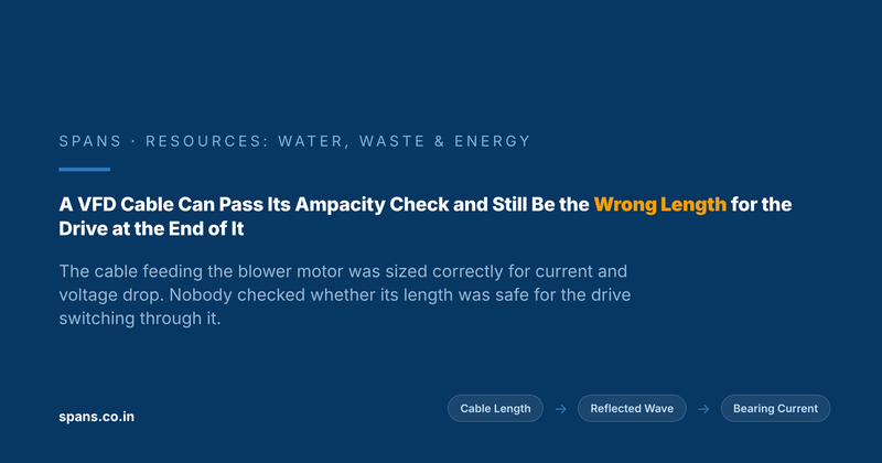
A VFD-to-Motor Cable Can Pass Every Sizing Check and Still Be the Wrong Length for the Drive Driving It
Every electrical contractor who has ever run a cable from a VFD to a blower or pump motor at an ETP or STP has sized it the same way: pick the conductor that ca..
Contents
Every electrical contractor who has ever run a cable from a VFD to a blower or pump motor at an ETP or STP has sized it the same way: pick the conductor that carries the motor's full-load current with margin, check the voltage drop over the run length against the usual 3 to 5 percent limit, and call it done. Both numbers are correct. Neither one asks the question that actually determines whether that cable is safe for a variable frequency drive to switch through, because a VFD doesn't just push current down a cable, it fires a fast-rising voltage pulse down it tens of thousands of times a second, and a cable's reaction to that pulse has almost nothing to do with its ampacity or its resistive drop.
A correct cable size and a safe cable length are different questions
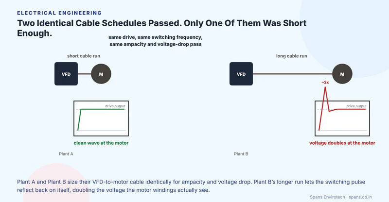
A VFD generates its output waveform by rapidly switching DC bus voltage on and off through pulse width modulation, and each of those switching edges sends a voltage pulse travelling down the motor cable at close to the speed of light. If the cable is short enough, the pulse reaches the motor, does its work, and the reflection that bounces back toward the drive arrives before the next pulse fires, so it does no particular harm. Once the cable exceeds what the industry calls a critical length, which drops as switching frequency rises and varies by cable type and motor voltage class, the geometry stops cooperating: the reflected wave arrives back at the motor terminals while the incident pulse is still rising, the two add together, and the voltage the motor's first winding turns actually see can run close to double what the drive nameplate suggests, arriving with a rate of voltage rise steep enough to stress insulation that was never designed for it. None of that shows up in an ampacity table or a voltage-drop spreadsheet, because both of those tools were built for 50 Hz sine waves, not for a variable-frequency drive's switched DC pulses.
Why the correct calculation keeps standing in for the real one
Ampacity and voltage drop are the checks every electrical engineer already knows how to run, documented in every cable-sizing handbook and demanded by every statutory inspection, so they get run reliably and signed off with confidence. Reflected-wave behaviour depends on variables most sizing exercises never touch: the drive's actual switching frequency (which an operator can change in the field long after commissioning), the specific cable's surge impedance, and the motor's own insulation rating, none of which appear on a standard cable schedule. A contractor who has correctly sized hundreds of motor feeders for ampacity has every reason to believe the job is done, because by the only standard they were trained to check against, it is. The length that was safe at a lower carrier frequency can become unsafe the day someone raises it to quieten an audible whine from the motor, with no cable change at all, and the faster switching edges that come with that higher frequency also radiate more electromagnetic interference along the same unshielded run, a separate nuisance that often arrives at the same time and gets blamed on the wrong cause.
This is the same shape of mistake we described in the piece on cable sizing against motor starting load: a feeder cable correctly sized against one electrical demand (there, starting inrush; here, steady running current) can still fail the demand nobody checked it against, because a cable schedule answers exactly the question it was built to answer and nothing else. The damage this particular gap causes is also slow enough to hide behind routine testing. A motor insulation resistance trend will eventually catch winding insulation that reflected-wave stress has been quietly degrading, but only after months of repeated dielectric punishment have already done the damage; by the time the megohm reading drops, the mechanism that caused it has been running since commissioning.
Reflected wave is not the only way an oversized gap between drive and motor bites back. The same PWM switching that creates the voltage pulse also induces a common-mode voltage on the motor shaft, and once that shaft voltage exceeds the dielectric strength of the thin oil film inside the bearing, it discharges across the raceway in a tiny electrostatic discharge event, repeated thousands of times a second. A single discharge does nothing. Months of them pit the bearing races into a fluted pattern that shows up as vibration and noise long before anyone thinks to connect it back to the drive feeding the motor, and a maintenance team chasing a "bad bearing batch" can replace the bearing two or three times before anyone asks why a healthy-looking motor keeps failing the same way.
Picture two identical blower motors at two plants, each fed from an identical VFD at the same switching frequency, with a cable run correctly sized for ampacity and voltage drop at both sites. Plant A's drive panel sits in the same room as the blower, a run of under ten metres. Plant B's electrical room was positioned for cable-tray routing convenience and panel ventilation, putting sixty metres of cable between drive and motor, a distance nobody flagged because the ampacity and voltage-drop numbers both still passed comfortably. Eighteen months in, Plant B starts replacing the blower motor's bearings every few months while Plant A's identical motor runs without incident, and the maintenance log blames bearing quality long before anyone traces it back to the one variable that was never on the cable schedule: distance.
What actually protects the motor at the end of that cable
The fix does not require abandoning ampacity and voltage-drop calculations, which remain necessary and correctly done. It requires adding the check those calculations were never built to make: comparing the actual cable run length against the drive manufacturer's stated critical length for that switching frequency and cable type, and treating any run approaching or exceeding it as its own design problem rather than an electrical footnote. Where routing genuinely requires a long run, that problem has real answers: a du/dt output filter or load reactor at the drive end slows the voltage rise enough to keep the reflected wave from doing damage, a shaft grounding ring or brush gives the common-mode discharge current a path that bypasses the bearing entirely, and specifying VFD-rated (inverter-duty) insulation on the motor itself buys real margin against whatever stress still gets through. Any one of those costs a fraction of a blower motor's bearing replacement and the production disruption around it, a comparison worth making against the plant's own wastewater treatment cost picture rather than discovering it motor by motor.
The electrical room that gets cable routing right for voltage drop but wrong for switching frequency has not made an error anyone will catch at commissioning. It has built a failure mode into the plant that waits for someone to change a switching frequency setting, or simply waits the eighteen months a fluted bearing needs, before it announces itself as a maintenance problem with no obvious electrical cause. If your plant's VFD-fed motors sit more than a short cable run from their drives, that distance is worth checking against the drive's own critical-length guidance with Spans' electrical engineering team before the next bearing failure gets written up as bad luck.
Spans
Spans empowers businesses around the world to grow faster and profitable while using less energy and water.
Visit Site