
A Grit Chamber Can Satisfy Its Detention Time Calculation and Still Never Remove the Grit
A grit chamber sits at the front of almost every ETP or STP that handles raw or partially screened sewage, and its design review usually asks one question: does..
Contents
A grit chamber sits at the front of almost every ETP or STP that handles raw or partially screened sewage, and its design review usually asks one question: does the chamber provide enough detention time at design flow for the grit to settle out. It is a reasonable question, it is usually answered correctly, and answering it correctly is not the same as the chamber actually removing grit, because grit removal is not governed by detention time at one flow. It is governed by channel velocity across every flow the plant actually sees, and a design that only checks one point on that range can satisfy its own calculation while failing most hours of most days.
Why grit separation needs a window, not a number
Grit chambers work because grit (sand, silt, eggshell fragments, the inorganic debris that enters a sewer) has a much higher specific gravity than the organic solids suspended alongside it, which means grit settles far faster under the same conditions, a relationship sedimentation design relies on directly. A channel's flow velocity has to sit inside a band that exploits that difference: fast enough that the lighter organic solids stay suspended and keep moving downstream where they belong, slow enough that the much-faster-settling grit actually has time to drop out. Push velocity too high and the chamber stops working for an almost opposite reason to the one most people assume, not because the grit doesn't have time to settle, but because turbulent, fast-moving flow keeps even the denser grit particles suspended rather than letting them lie still on the channel floor. Drop velocity too low and organic solids start settling out alongside the grit, which means the chamber stops being a grit chamber and starts being an unintended, unmanaged primary settling tank at the front of the plant.
Detention time is a design-flow number. Velocity is not.
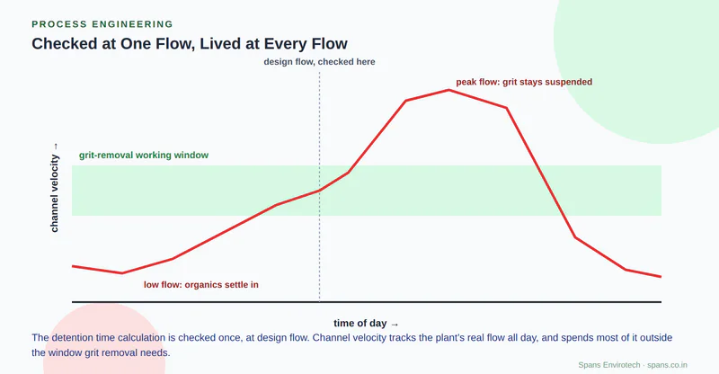
A detention time calculation is checked at a single design flow, usually peak flow, because that is the flow condition the chamber's volume has to be adequate for. Velocity is a different kind of number entirely. In a channel of fixed cross-section, velocity is flow divided by area, which means it tracks the plant's actual flow directly and continuously, rising and falling with every shift in influent across a day, a week, a storm event. A chamber whose geometry was sized to hit the right detention time at design flow has no particular reason to also sit inside the correct velocity window at every other flow the plant experiences, because nothing in a detention-time check asks that question. The two numbers look like they are testing the same design. They are not.
This is the same shape of mistake we described in the piece on equalization tank sizing: a hydraulic retention time calculation can be entirely correct and still miss the parameter that actually determines whether the unit does its job, because HRT and mixing intensity are different questions wearing the same units. Here, detention time and velocity are the same kind of mismatch at the front of the plant instead of the middle of it: a chamber can be sized exactly right for the number the design review checks and still miss the number that governs what actually happens to the grit.
What a flat flow assumption misses in practice
A plant's real flow is never flat. Domestic sewage flow typically troughs overnight and peaks during morning and evening use, and a chamber built around a single rectangular channel with a fixed cross-section will see velocity swing across that whole daily range, not sit calmly at the figure used in the design calculation. At the low end, usually the dead of night, velocity can fall well below the window grit removal needs, and organic solids that should have stayed in suspension start settling out with the grit instead. That carryover does not announce itself at the grit chamber. It shows up later: putrescible organic material mixed into what is supposed to be inert grit, creating odour at the grit handling and disposal point, and adding an unplanned organic load to whatever downstream process receives the separated grit.
At the high end, during a wet-weather event or a plant running above its usual flow, velocity can climb past the upper bound of the window, and grit that would ordinarily settle stays suspended and travels straight through the chamber. That grit does not just vanish from the removal statistics. It carries downstream into pumps, where it accelerates impeller wear, into aeration basins, where it accumulates on the floor and quietly eats into available volume over months, and into any equipment downstream that was never designed to handle abrasive inorganic solids as a routine input.
Picture a municipal STP, the first stage of the treatment relay handing raw sewage off to everything downstream of it, with a single rectangular grit channel sized correctly for peak design flow, commissioned, and passing every acceptance test run during the day shift when flow happened to sit close to that design figure. Months later an operator notices the grit skips at the handling point smell noticeably worse than they used to, and separately, a maintenance team flags unusually fast wear on a downstream pump impeller. Nobody connects the two observations to the grit chamber, because the chamber was tested and it passed, and neither symptom looks like a grit removal problem on its own. The actual cause is the same channel operating correctly at one flow and badly everywhere else: overnight low flow lets organics settle into the grit (the odour), and daytime peaks beyond the original design push velocity too high for grit to settle at all (the pump wear). One chamber, one unexamined assumption, two unrelated-looking symptoms showing up in two different parts of the plant.
Designing for the range instead of the point
The fix available to a design review is not a bigger chamber, which mostly just changes where on the flow range the mismatch occurs rather than removing it. It is a chamber geometry or control strategy that keeps velocity inside its working window across the plant's actual flow range, not just at the one flow the detention time calculation was checked against. A parabolic or trapezoidal channel section, a flow-proportional weir at the outlet, or a velocity-control gate are all standard answers to exactly this problem, and each one works by changing the channel's effective cross-section as flow changes, so that velocity stays closer to constant even as flow does not. CPHEEO's sewerage and sewage treatment design guidance is the relevant starting reference for sizing these control features against Indian flow conditions rather than importing a design built around a different country's diurnal flow pattern.
A grit chamber that was only ever checked at design flow can pass every calculation on its data sheet and still spend most of its operating life outside the velocity window that makes grit removal work at all. If your plant's headworks was sized against a single flow point rather than the range it actually sees, that is worth reviewing with Spans' process engineering team before the grit shows up somewhere it was never meant to be.
Spans
Spans empowers businesses around the world to grow faster and profitable while using less energy and water.
Visit Site